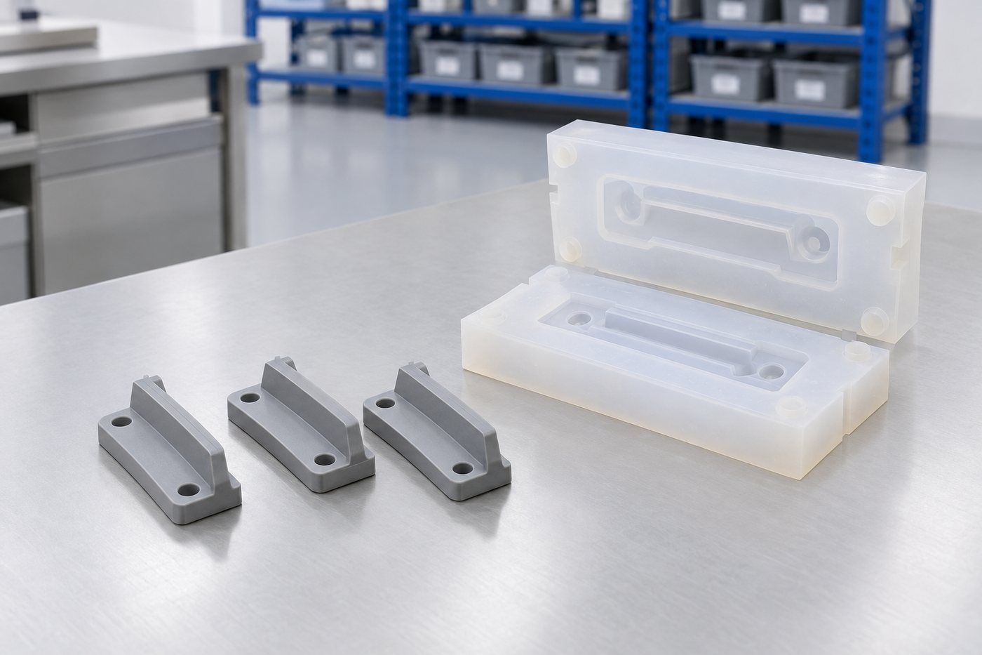
Vacuum cast moulds
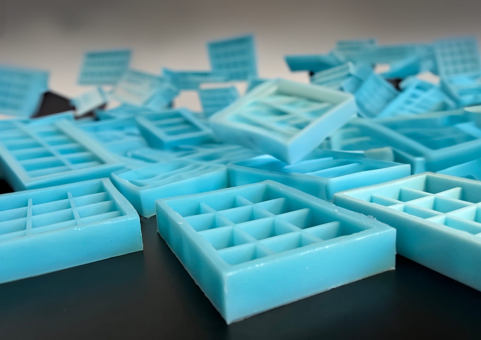
We cast under vacuum to remove air before curing. This process makes a feature this fine repeatable, rather than relying on luck.
Vacuum castingProject record · Aerospace subcontract · Vacuum cast route
An aerospace subcontractor sent us a drawing with one feature far finer than anything we had previously held in a soft tool. The rest of the part was ordinary. But that single feature determined the entire job.
The brief
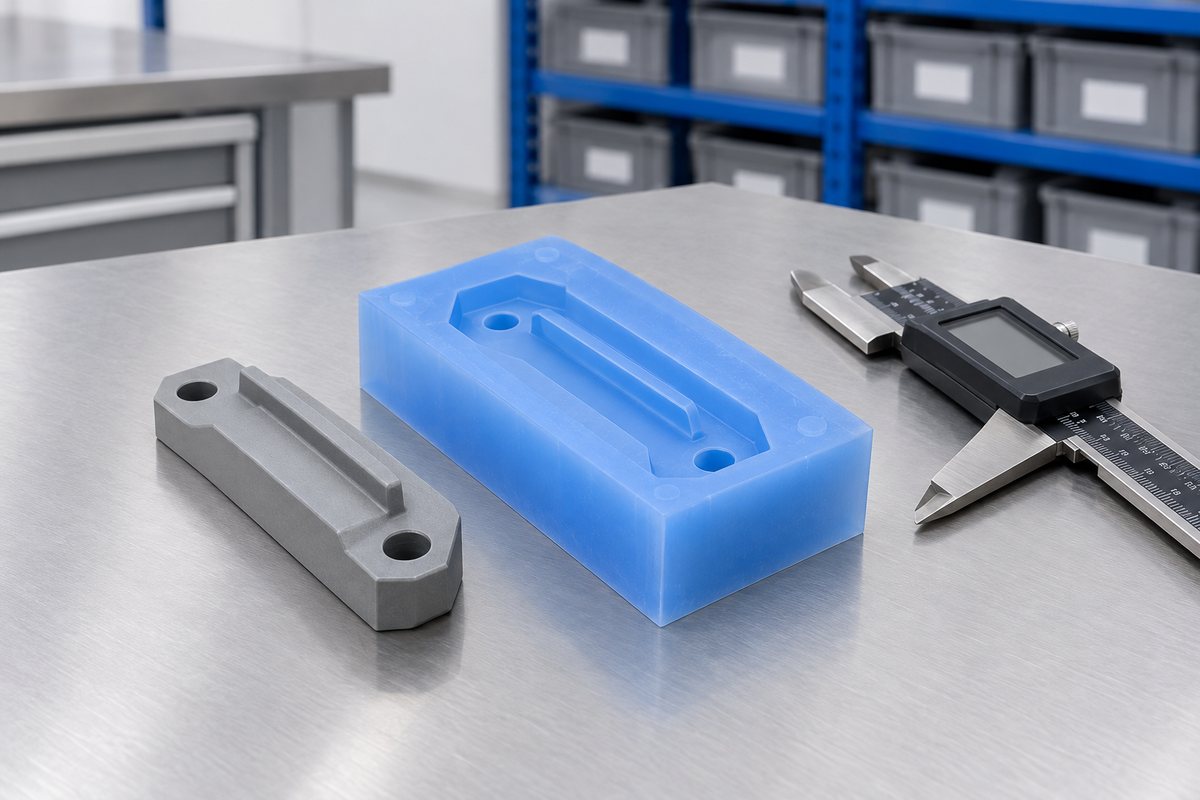
This enquiry came from a subcontract engineering business supplying into aerospace. They had a small cast component with the design complete, the drawing finalised and sign-off from their own customer. They wanted it made in silicone rather than the rigid material used for the prototype, with repeatable results across a development batch.
At first glance, the drawing looked straightforward: generous walls, a sensible draft and nothing likely to fight a mould. Look more closely, though, and one face carried a single raised detail finer than anything we had held in a soft tool before. The drawing note beside it made clear that this detail was the purpose of the part, not decoration.
The whole job came down to one question: could that feature be filled consistently in a mould we could actually make? We were honest that we did not know yet, even though that is not what anyone wants to hear. We asked for the master and permission to run trials before quoting for a batch.
That is the honest way to handle work like this: prove the hard bit first, then price the easy bit.
The problem
In a normal casting, a trapped bubble is usually just a blemish. You spot a pinhole, decide whether it matters, and usually it doesn't. But when the feature is this fine, a single bubble isn't a blemish at all: it fills the whole feature. The detail is simply missing. The rest of the part looks clean, which can be worse than a visibly wrong part.
The first hand pours showed the point clearly, without needing an argument. Under a loupe, roughly one casting in three had the feature fully formed. In the others, it was either partly formed or missing. The failures showed no consistent pattern, because air does not queue up politely.
Two mechanisms were at work. Air already dissolved in the mixed silicone was released as the material sat in the fine cavity. Air was also carried in during the pour, with nowhere to escape from a blind detail. Tackling either issue on its own would not have solved the problem.
We also had to set a limit of our own. A soft mould breathes and moves, so for a detail this small, the mould face needs to be as close to inert as possible. That made grade selection just as important as the process itself.

Illustrative schematic. Real tools include additional detail (runners, vents, ejector positions).
What we changed
We made four changes, one at a time, so we knew exactly which change earned its place.
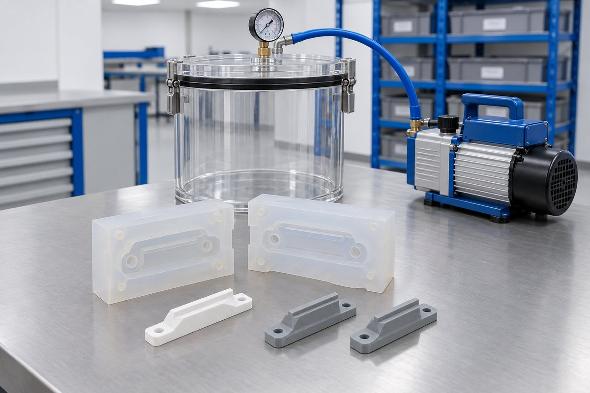
We draw the material down under vacuum until it has finished rising and falling back. Air already in the mix cannot be pushed out of fine detail later, so it needs to come out first.
We cast the mould itself under vacuum against the master. This gives the mould face crisp detail, rather than carrying our own casting faults into every part it then makes.
We moved the fill point so the silicone reached the fine face last, rather than first, with the detail positioned at the high point of the cavity. Air goes where you let it go.
For the trial batches, we used a controlled cabinet rather than the bench. A warm draught across one side of a small mould can affect repeatability, so controlled curing avoids that variable.
During development, we checked every casting under magnification and logged the result. Sampling could have hidden the intermittent fault we were working to eliminate.
The stages
Drag the timeline left and right, or use the arrow keys. Each stage explains what happens and roughly how long it takes.
Drag · tap a stage for detail
Total working time on a job of this shape: about 5 weeks (38 working days). Lead times shift with drawing changes, sign-off pace and material availability.
Route logic
Rather than quote a figure that would only be right for one job, here is a worked example, based on a realistic project of this shape. Your quote follows the same shape, with your part, your volume and your material.
An aerospace supplier needing 40 parts a month, tight FAI paperwork.
| Master pattern (SLA + hand finish) | £680 one-off |
|---|---|
| Two-part vacuum-cast mould | £1,150 one-off |
| Tooling amortised over 480 parts/year | ≈ £3.81 per part |
| Cast, degas, trim, inspect | ≈ £14.50 per part |
| Landed cost per part | ≈ £18.31 |
Quote assumes RTV-2 platinum silicone, 40 Shore A, individual FAI on the first article and PPAP-level paperwork per batch.
You were the third supplier we asked and the first to say the feature might not be possible. That honesty is why we believed you when the parts arrived with it included.
Engineering buyer, aerospace subcontract manufacturer
Behind the work
Three pieces of our work feature here. Each has its own page explaining what it suits and where it stops.
We cast under vacuum to remove air before curing. This process makes a feature this fine repeatable, rather than relying on luck.
Vacuum casting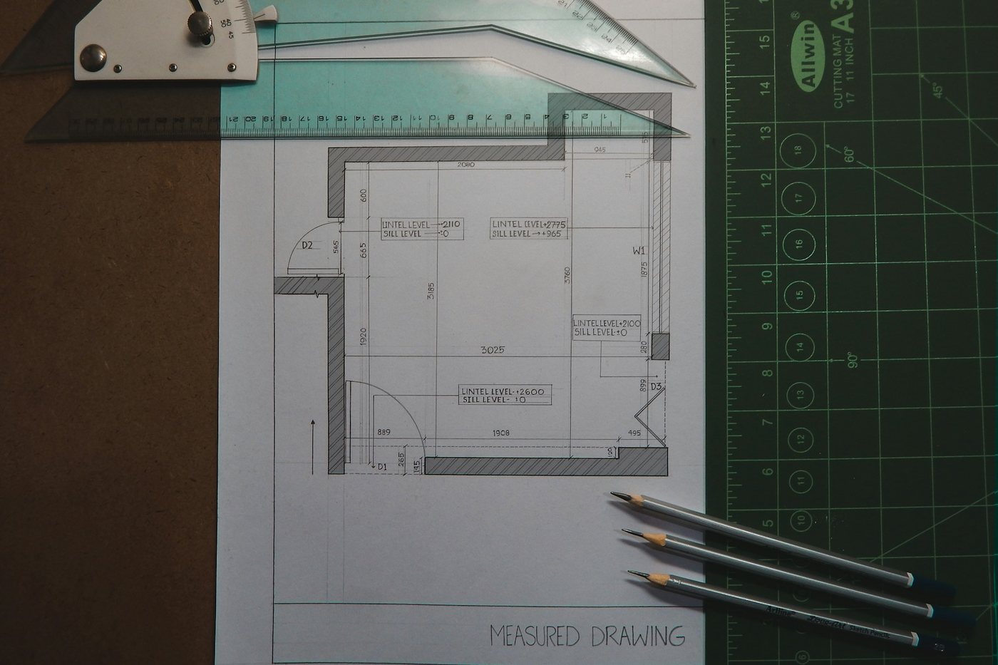
We read your drawing for draft, the split line and the one feature that will decide the route. This is where we discuss the fill point.
CAD and DFM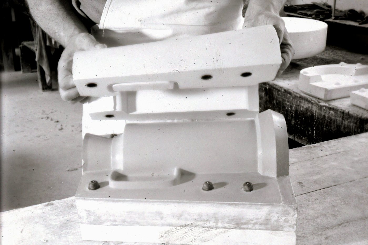
Development tooling is for a part whose drawing can still change. It is inexpensive to alter and deliberately not intended to be the tool you run for years.
Prototype toolingMore records
Fine moulded relief on a curved strap face, proven in a soft tool before the steel was cut.
Watch strap logosThe thin cast part curled at the corners until the mould was rebuilt on a rigid base.
Electrical patchHand-modelled pattern: finding the cause of a tacky mould face
Jewellery masterNext step
Intermittent fill on a small detail is rarely a mystery. It usually comes down to dissolved air, entrained air, the wrong fill point, or a mould face that was not crisp to begin with. The key is identifying which of these four issues you have. That takes a sample, not just a description.
Please send us the part or the failed castings, and let us know what proportion come out right. A batch that fails half the time can tell us more than one that fails only once. If we think the feature needs a hard tool rather than a soft one, we will say so before you have paid us for a mould that cannot hold it.
If your geometry is still in CAD, we prefer to see it there, because moving a fill point on screen is free.
At a glance
Which route suits your quantity
Swipe to see the whole diagram
Ready to start?
Send us a drawing, photograph or sample. We'll come back with a mould strategy, material recommendation and price.
Real people, a real workshop
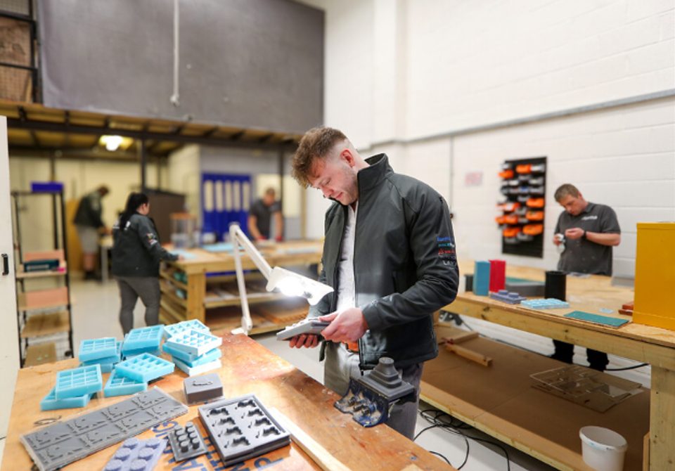
No call centre and no middlemen. When you contact TCI Mouldings, you speak to the team who design, build and check your mould.

 Thomas LaneManaging Director
 George PrestonDesign & Project Manager
 Kelly BallingerHead of Partnerships
 Jim AndertonProduction Manager
 TheodoreEmployee Welfare